Components
The positions of the components can be modified, and to do so it is very important to a robust structure with high precision. Worth to remind that in a holographic setup a tiny variation in these positions can mean defocused images, alias and replica phenomena, or even unfeasible reconstructions. In order to overcome these issues was designed an aluminum structure and used professional optical components were acquired on ThorLabs Store.
Optical Components
The table below shows the basic optical components used to assemble the interferometric microscope device.
| Components | Description | Specification |
|---|---|---|
| Source Light | Collimated Laser-Diode-Pumped DPSS Laser Module | Wavelength = 532 nm, w = 4.5 mW, Round Beam, Ø11 mm Housing. |
| Battery | Battery Pack for CPS Laser Diodes | 5 VDC, 10 000 mAh |
| Beam Expander | Wavelength = 532 nm, Expansion Ratio: 5X, Size: 70.5 mm, Transmission: >96% | |
| Microchannel Chip | Channel Volume: 11.8 micro liter$, Channel Width: 1.0 micrometer, Channel Depth: 0.2 micro liter | |
| Grating | ||
| Lens | Mounted Geltech™ Lens | f=6.24mm, AR Coated 1050nm-1550nm |
| Digital Camera | See3CAM_CU55M | 5MP Monochrome, Pixel Size: 2.2 micrometer |
Structural Components
The structural components make possible the right placement of the optical components and a robust system base to minimize the vibrations effects in the hologram acquisition.
System Base
The base of the system was designed to be robust, in order to keep the optical components aligned correctly and to try deal with the vibrations of these components. The figure below depicts the drawing of the system, indicating the profile used and the assemble.
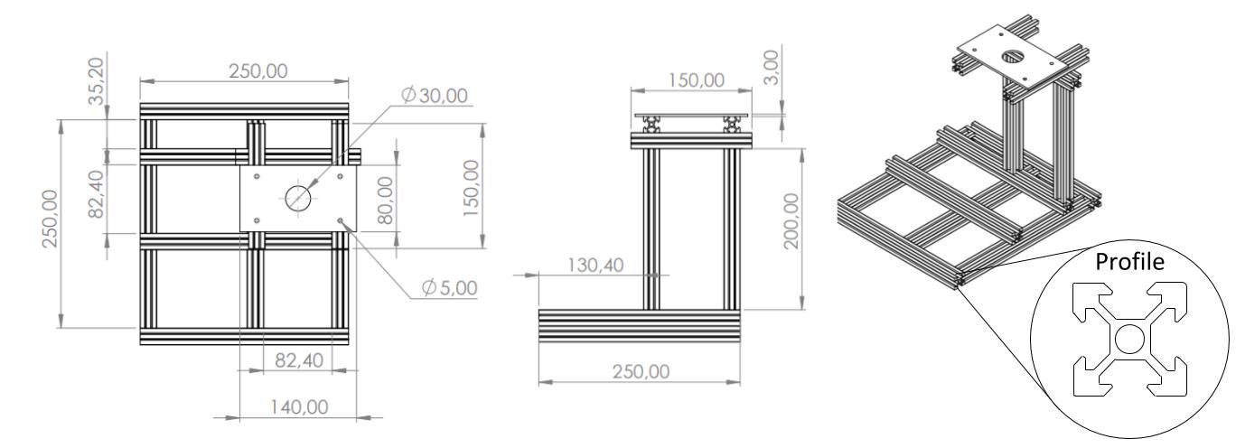
All the system is formed by 12 aluminum bars with a v-slot profile. This profile makes easier the assemble and allows the exchange of the pieces, letting the system adaptable. Of those 12 bars, 7 bars of 250mm are used to the structure bases; 2 bars of 200mm to the vertical laser support; 3 bars of 150mm to the horizontal laser support; and a plate 150x80x3mm to the laser holder.
Optical Components Holders
To move the optical components are used professional components that are fixed on the system base and are able to change the positions of these components, making the system able to change according to application and easily adjustable to acquire better holograms. The table below show these components.
| Components | Description | Specification |
|---|---|---|
| Lens | XR25-XZ Assembly Kit XR25-B1 Baseplate} XR25P 25 mm Travel Stage ST1XY-S - Translator (micrometer drives) | These components allow perform the right displacements in the lens in all directions. |
| Camera | XR25-XZ Assembly Kit XR25-B1 Baseplate XR25P 25 mm Travel Stage CH1A - Fixed Cylindrical Mounts} | These components allow perform the right camera displacement in the Z direction. The CH1 is an adapted component that can be replaced for any holder that possibilities fix the camera to baseplate. |
| Grating | FP01 - Plate Holders | This holder is a adapted component to fix the grating to aluminum structure and also can be replaced for a similar component. |
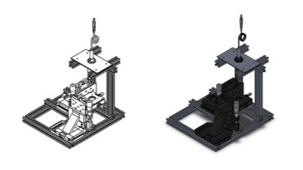
Then, the final 3D structure assembled is
Designed Components
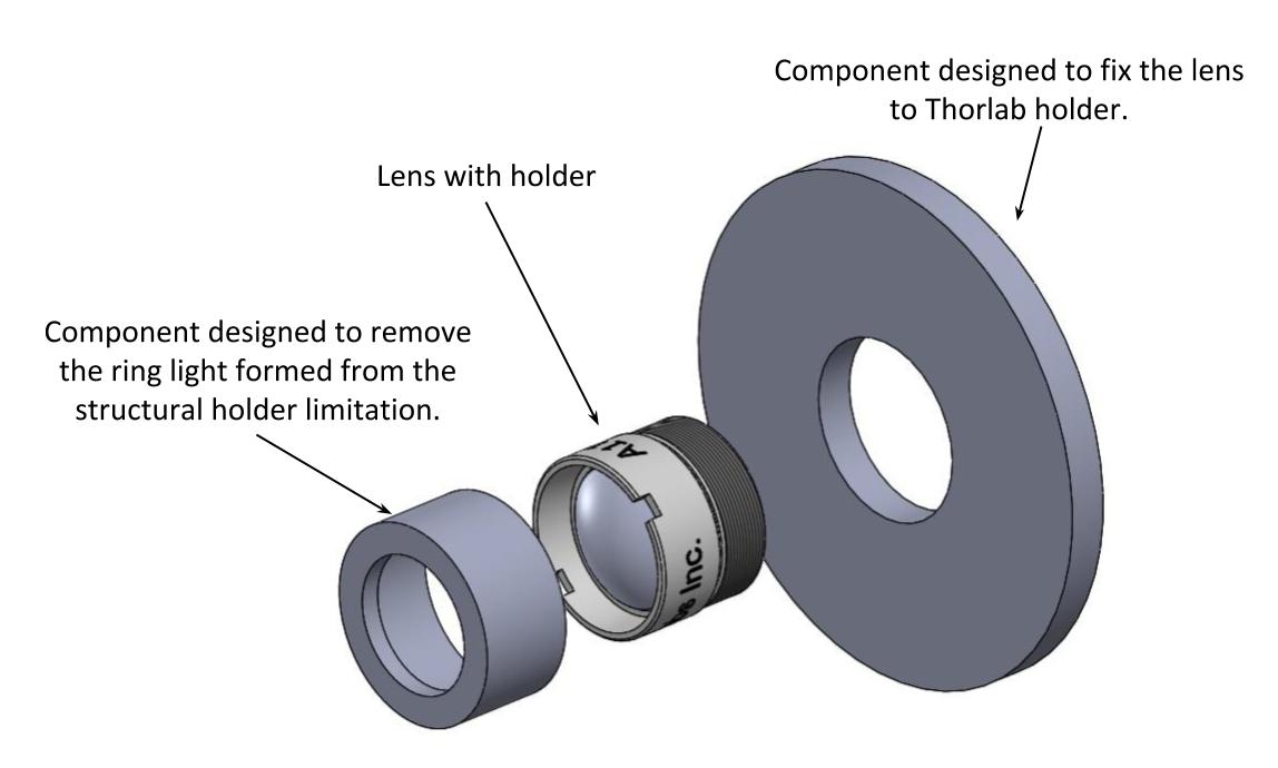
As the lens diameter is smaller than the structural component aperture used to hold the lens, a little piece was designed to assemble correctly these two components. Besides that, in the experiment setup, it was found one problem related to the lens holder that it needed to make another piece to solve. Basically, the acquired lens holder has a little gap between the holder structure and the lens. When the laser beam impinges in the lens, a light ring is formed after the lens plane, interfering in the fringes formation. So a little component was used in the top of the lens holder to block the light that was going directly to the lens border. These two components are shown in figure below.
Other Components
One point that should be taken into account is when the optical components ordered are of different brands. In our case, the beam expander and the laser were acquired from different stores. Because of that, the two components were not compatible to put them together with only one holder. For this, it was ordered more three components to adapt and keep both of them co-linear. The table below outlines these components.
| Components | Description | Brand |
|---|---|---|
| Adapter | AD11F - Ø11 mm Cylindrical | Thorlabs |
| Lens Tube | SM1M15 - 1.5" Long, Two Retaining | Thorlabs |
| Adapter | SM1A10 - External SM1 Threads Internal C-Mount Threads | Thorlabs |
| Adapter | Female M22 x 0.75 to Male | EdmundOptics |
Pumping Module
In order to make easier the water sample collection, it was designed a pumping module. Composed of one pump, one controller, and both the inlet and outlet tubes, the sample can be inserted into the system with a bi-directional controlled flow.
| Components | Description |
|---|---|
| Pump | Peristaltic Pump - 6-12 VDC Input |
| Controller | Regulator - 12VDC Input |
| In/Outlets | Diameter of 1 mm |